Dynamic Transformation (DT) 
The effective suppression of the Lift-Off is among other a result of the
earlier described Frequency Difference Method (FDM).
In order to maintain a good accuracy over a large Lift-Off working range
and further suppress oscillation marks etc., an extra signal transformation
circuit, Dynamic Transformation, DT is added to the FDM.
This circuit can briefly be said to compensate for the effects of different
current penetration depths caused by eddy current measuring with several
frequencies.
Even if the principle for DELTATEST is theoretically simple, it is not
possible to describe it in a few words. Using the enclosed figures 4 and 5,
a simplified explanation of problems and solutions can be given.
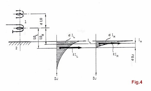
The sensor coil is supplied with current with one high (WH) and one
low (WL) frequency.
The induced magnetic flow from the sensor induces partial currents,
d(IH) and d(IL) respectively of corresponding frequency content in
the test object, unequally for different frequencies as a result of
different current penetration.
If all partial currents for each frequency were to be replaced with
a new fictive total current, called E(IH) and E(IL) respectively, these
currents would be found on different depths, which is shown in Fig. 4.
These fictive currents influence the sensor to the same extent as the
total effect fram all partial currents.
It is important to note that the influence on the sensor by the fictive
currents also is greatly distance dependent, wich means that the influence
is a function of the Lift-Off distance.
When, as described in the VTF-section, this technique is used to equalise
dLOL and dLOH, to achieve a sufficient distance suppression, this is
working satisfactory at the Lift-Off distance in question where the
VTF optimisation was done.
If the VTF adjustment is done at the distance which is marked with
continuously coil symbol in the figure, this adjustment refers to
LOL and LOH respectively and the distance suppressions is optimised.
If the distance from the coil to the test surface is increased by a distance
dLO, the influence on the coil from the fictive currents will not follow
each other equally for the difference frequencies because of the difference
in current penetration depth dDj.
This means that the VTF adjustment is only optimised for one LO-distance – marked
with continuous coil symbol in Fig. 4.
A VTF adjustment, which is not optimised, will result in reduced distance
suppression with related risk for false crack signals. (Over-detection as
well as under-detection)
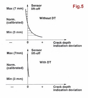
To eliminate this drawback the DYNAMIC TRANSFORMATION (DT) was developed
by TÖRNBLOMS KVALITETSKONTROLL.
It can be described as follows:
The distance between the sensor and the surface is measuered, simultaneously,
by the same sensor that measures the crack signal.
The distance signal adjusts automatically (electronically) the VTF circuits,
which then are optimised for the whole LO-working range.
This improvement, Fig. 5, is of fundamental importance in achieving high
detection accuracy, demonstrated already by the first systems for continuous
hot slab-inspection.
|